
 EnglishCurrent
 德语
德语 阿拉伯语
阿拉伯语 法语
法语 印尼语
印尼语 日语
日语 韩语
韩语 马来语
马来语 葡萄牙语
葡萄牙语 俄语
俄语 西班牙语
西班牙语 泰语
泰语 土耳其语
土耳其语 越南语
越南语

Cleanroom HVAC and Air Handling Equipment
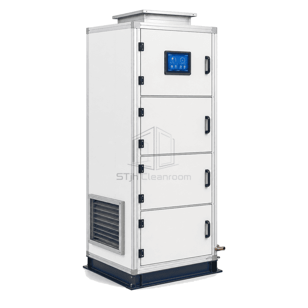
Vertical Air Handling Unit
A stacked upflow or downflow air handler that reduces plant-room footprint while retaining full filter, coil and fan functionality.
- Small Floor Footprint
- Upflow or Downflow Layout
- Stacked Service Sections
- Rigid Vertical Frame
Product Introduction
The vertical air handling unit stacks treatment components to use room height instead of long floor area. Air may enter low and discharge upward, or follow a downflow path to a raised floor or low duct. Filters, coils and fan sections are separated by accessible service zones, and the frame is reinforced for the vertical component load. Drain and trap geometry are arranged for the selected casing pressure, while lifting points and removable panels support installation in compact plant rooms.
Key Features
Upflow and downflow discharge options align with high-level or underfloor duct systems.
Reinforced base and frame transfer fan, coil and filter loads through the vertical casing.
Dedicated access doors keep filter and wet-section service points reachable from one side.
Customer Product Concerns
Stacking components saves floor space only if service access, drainage and structural loads are addressed in the vertical arrangement.
A horizontal unit blocks the only service aisle in a small plant room.Vertical stacking shortens the footprint while preserving treatment functions.
The discharge duct must turn sharply and adds unnecessary pressure loss.Upflow or downflow discharge connects directly to the building riser or floor plenum.
Upper filters are difficult to lift and remove safely.Filter stages are positioned at practical service height with slide-out tracks.
Condensate trap height is insufficient under negative casing pressure.The base frame provides clearance for a trap sized to the actual section pressure.
Typical Applications
Compact cleanroom plant roomsHospital mechanical closetsLaboratory retrofit shaftsVertical supply risersUnderfloor clean-air systems
Technical Parameters
Typical casing values for an insulated vertical air handling unit are listed below.
| Core Material | Polyurethane or mineral-wool insulation in reinforced double-skin panels |
|---|---|
| Panel Thickness | 40–60 mm insulated panel |
| Effective Width | 800–2400 mm nominal casing width |
| Maximum Length | Up to 3500 mm horizontal base length for stacked configuration |
| Steel Facing Thickness | 0.6–1.0 mm casing skins with reinforced base members |
| Core Density | 41–45 kg/m³ polyurethane or 84–100 kg/m³ mineral wool |
| Thermal Conductivity | 0.022–0.040 W/(m·K) according to panel core |
| Surface Finish | Powder-coated galvanized exterior with galvanized or stainless inner lining |
| Joint Type | Compression-gasketed stacked panels on bolted structural base and vertical frame |
| Customization | Available based on the intended application and operating environment. |
Available Options
Upflow, downflow or side dischargeChilled-water, hot-water or DX coilsEC plug fan or fan arrayBottom or side return-air connection
Planning a Vertical Air Handling Unit specification?
Send us your dimensions, installation conditions, performance targets and required surface finish.