
 EnglishCurrent
 德语
德语 阿拉伯语
阿拉伯语 法语
法语 印尼语
印尼语 日语
日语 韩语
韩语 马来语
马来语 葡萄牙语
葡萄牙语 俄语
俄语 西班牙语
西班牙语 泰语
泰语 土耳其语
土耳其语 越南语
越南语

Cleanroom Air Distribution Systems
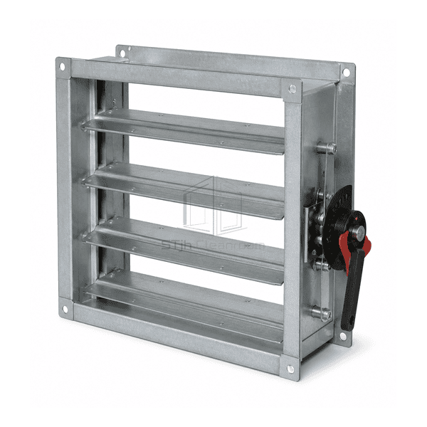
Manual Volume Control Damper
A locking quadrant damper with linked galvanized blades for setting and retaining the balancing position of a rectangular duct branch.
- Locking Manual Quadrant
- Opposed 3V Blade Bank
- Concealed Frame Linkage
- Permanent Branch Balancing
Product Introduction
The manual volume control damper places a bank of linked 3V blades inside a rigid galvanized channel frame. Turning the external quadrant rotates the blade shafts together, allowing the balancing technician to establish the required branch resistance and then lock the position mechanically. Opposed blade motion provides more even downstream velocity distribution than a single flap at intermediate positions. The drive linkage is enclosed within the frame, leaving the airway clear and protecting moving parts from accidental contact.
Key Features
Opposed 3V blades divide the throttling area across the full frame for smoother branch balancing.
Concealed linkage reduces obstruction in the airway and shields connecting bars from handling damage.
Channel-frame flange options support duct insertion, surface mounting or connection to an equipment opening.
Customer Product Concerns
A manual damper should give the balancer fine position control, remain locked after commissioning and avoid creating a severely biased downstream velocity profile.
A loose handle creeps open after the branch has been balanced.A positive locking quadrant clamps the shaft at the recorded blade position.
A single large blade sends a concentrated jet toward one side of the downstream duct.Opposed blade operation divides the opening and produces a more distributed throttled flow.
External linkage is bent by insulation work or routine ceiling access.Link bars concealed inside the channel frame leave only the protected operator outside the casing.
The adjustment handle becomes buried beneath duct insulation.An extended shaft and stand-off quadrant preserve visible, reachable adjustment after insulation is applied.
Typical Applications
Cleanroom supply branch balancingGeneral exhaust duct commissioningAir-handling unit internal bypassesReturn-air grille branch controlFixed-volume process ventilation
Technical Parameters
Typical construction data for a galvanized rectangular manual balancing damper are listed below.
| Core Material | Galvanized-steel 3V blades with plated steel shafts, concealed linkage and polymer bearings |
|---|---|
| Panel Thickness | 1.5 mm formed galvanized control blades |
| Effective Width | 152–1219 mm nominal single-section frame width |
| Maximum Length | Up to 1880 mm single-section frame height |
| Steel Facing Thickness | 1.5 mm galvanized channel frame |
| Core Density | Approximately 7850 kg/m³ for galvanized steel blades |
| Thermal Conductivity | Approximately 45–55 W/(m·K) for the carbon-steel blade material |
| Surface Finish | Mill-galvanized blade and frame surfaces with zinc-plated operating hardware |
| Joint Type | Flanged channel frame with linked opposed blades and external locking quadrant |
| Customization | Available based on the intended application and operating environment. |
Available Options
Parallel or opposed blade actionSingle, reversed or double flange frameExtended shaft for insulated ducts304 or 316 stainless-steel construction
Planning a Manual Volume Control Damper specification?
Send us your dimensions, installation conditions, performance targets and required surface finish.