
 EnglishCurrent
 德语
德语 阿拉伯语
阿拉伯语 法语
法语 印尼语
印尼语 日语
日语 韩语
韩语 马来语
马来语 葡萄牙语
葡萄牙语 俄语
俄语 西班牙语
西班牙语 泰语
泰语 土耳其语
土耳其语 越南语
越南语

Cleanroom HVAC and Air Handling Equipment
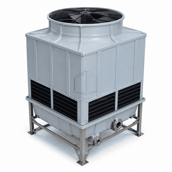
Induced-Draft Counterflow Cooling Tower
A compact evaporative heat-rejection tower that draws air upward through wetted fill while condenser water descends into an accessible collection basin.
- Counterflow Air-Water Contact
- Top-Mounted Induced Draft
- Corrosion-Resistant FRP Shell
- Serviceable Fill and Basin
Product Introduction
The induced-draft counterflow tower uses a top axial fan to draw ambient air upward against warm condenser water distributed above the fill. Evaporation removes heat before cooled water collects in the lower basin and returns to the refrigeration plant. A square FRP casing, removable louvers and modular fill pack provide a compact alternative to crossflow arrangements where footprint matters.
Key Features
The fan at the discharge draws air uniformly through lower inlet louvers and reduces recirculation at the intake.
FRP casing panels and stainless support members resist continuous wet service and treatment chemistry.
Access doors, removable fill cassettes and an open basin support inspection of water-contact components.
Customer Product Concerns
A cooling tower must reject the design load while controlling footprint, water distribution and maintenance access.
Limited roof area restricts the size of heat-rejection equipment.A vertical counterflow path concentrates fill depth and fan discharge within a compact square plan.
Uneven spray distribution leaves dry fill zones and reduces capacity.A full-coverage header and serviceable nozzles wet the modular fill pack uniformly.
Drift can carry treatment chemicals beyond the tower.Dedicated drift eliminators change exhaust-air direction and capture entrained droplets.
Basin sediment blocks strainers and accelerates corrosion.Accessible sloped basin surfaces, drain points and removable strainers simplify routine cleaning.
Typical Applications
Cleanroom chiller condenser-water systemsPharmaceutical process-cooling loopsHospital central plantsElectronics-factory HVACIndustrial refrigeration heat rejection
Technical Parameters
Representative physical construction ranges for a modular counterflow tower are listed below.
| Core Material | PVC fill media inside fiber-reinforced polymer casing |
|---|---|
| Panel Thickness | 3-6 mm molded FRP casing panel thickness |
| Effective Width | 1000-3200 mm nominal tower cell width |
| Maximum Length | Up to 6500 mm for multi-cell assemblies |
| Steel Facing Thickness | 1.5-3.0 mm stainless or hot-dip-galvanized basin/support sheet |
| Core Density | 30-60 kg/m³ typical PVC fill-pack density |
| Thermal Conductivity | Approximately 0.19 W/(m·K) for rigid PVC fill material |
| Surface Finish | Smooth UV-stabilized FRP exterior with passivated or galvanized hardware |
| Joint Type | Bolted gasketed casing panels with modular clipped fill cassettes and flanged water ports |
| Customization | Available based on the intended application and operating environment. |
Available Options
Single-cell or multi-cell configurationPVC or higher-temperature polypropylene fillVariable-speed fan drive and vibration switchStainless basin, electric basin heater and low-noise fan
Planning a Induced-Draft Counterflow Cooling Tower specification?
Send us your dimensions, installation conditions, performance targets and required surface finish.