
 EnglishCurrent
 德语
德语 阿拉伯语
阿拉伯语 法语
法语 印尼语
印尼语 日语
日语 韩语
韩语 马来语
马来语 葡萄牙语
葡萄牙语 俄语
俄语 西班牙语
西班牙语 泰语
泰语 土耳其语
土耳其语 越南语
越南语

Cleanroom Control and Environmental Monitoring Systems
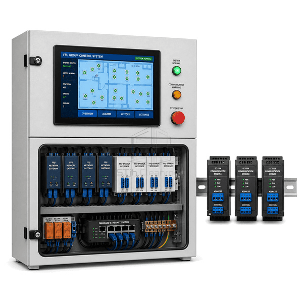
FFU Group Control System
A networked controller that supervises large banks of fan filter units, distributes speed setpoints and identifies individual FFU faults from one operator panel.
- Individual FFU Addressing
- Grouped Speed Commands
- Live Motor Feedback
- Fault Location by Unit
Product Introduction
The FFU group control system connects individually addressed EC fan filter units through dedicated communication branches and industrial gateways. Operators can start, stop or change speed by room, zone or selected unit while receiving actual speed, current and fault status from each fan. Scheduled occupied and setback modes reduce unnecessary fan energy outside production periods. Branch segmentation keeps troubleshooting practical in large ceilings because a communication issue can be isolated without losing visibility of every cleanroom zone.
Key Features
Zone commands change multiple EC fan speed setpoints without editing every unit separately.
Returned speed, current and alarm states reveal stalled or disconnected FFUs quickly.
Segmented gateways support orderly expansion across multiple cleanroom ceiling grids.
Customer Product Concerns
A large FFU ceiling needs centralized control without making a single branch fault difficult to diagnose or service.
Technicians cannot identify which fan in a dense ceiling grid has failed.Addressed status feedback links each alarm to a room coordinate and FFU number.
Manual speed adjustment creates inconsistent airflow across adjacent zones.Group setpoints apply a coordinated command to every selected FFU branch.
Full-speed operation during idle hours wastes fan energy.Scheduled occupied and setback commands reduce speed when process demand is lower.
One communication fault can obscure a large number of ceiling units.Multiple isolated branches and gateways limit the affected section and preserve the remaining network.
Typical Applications
Semiconductor cleanroom ceilingsPharmaceutical filling suitesElectronics assembly cleanroomsModular cleanroom installations
Technical Parameters
Typical construction for an FFU group control cabinet serving networked EC fan filter units is listed below.
| Core Material | Powder-coated steel cabinet with FR-4 control boards, isolated RS-485 interfaces and copper terminals |
|---|---|
| Panel Thickness | 180-350 mm cabinet depth |
| Effective Width | 500-1000 mm enclosure width |
| Maximum Length | Up to 1800 mm enclosure height |
| Steel Facing Thickness | 1.2-1.8 mm powder-coated steel panels |
| Core Density | 7800-8050 kg/m³ for steel enclosure components |
| Thermal Conductivity | 45-60 W/(m·K) for steel structural parts |
| Surface Finish | Light-gray textured powder coat with blue HMI bezel and labeled branch indicators |
| Joint Type | DIN-rail modular cabinet with segregated power and multi-branch Modbus terminal sections |
| Customization | Available based on the intended application and operating environment. |
Available Options
Modbus RTU or TCP gatewaysTouchscreen ceiling mapOccupied and setback schedulesRedundant communication branches
Planning a FFU Group Control System specification?
Send us your dimensions, installation conditions, performance targets and required surface finish.