
 日本語
日本語 ドイツ人。
ドイツ人。 アラビア語:アラビア語
 フランス語で
 インドネシア語
 日本語で。流れ
 韓国語
韓国語 マレー語
マレー語 ポルトガル語
 ロシア語
ロシア語 スペイン語
スペイン語 タイ語
タイ語 トルコ語
トルコ語 ベトナム語
ベトナム語

クリーンルーム管理 · 環境モニタリングシステム
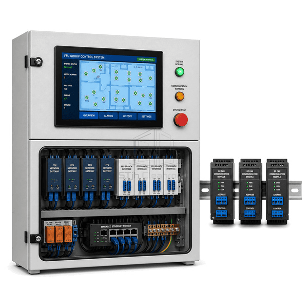
FFU グループ制御システム
A networked controller that supervises large banks of fan filter units, distributes speed setpoints and identifies individual FFU faults from one operator panel.
- Individual FFU Addressing
- Grouped Speed Commands
- Live Motor Feedback
- Fault Location by Unit
商品紹介
The FFU group control system connects individually addressed EC fan filter units through dedicated communication branches and industrial gateways. Operators can start, stop or change speed by room, zone or selected unit while receiving actual speed, current and fault status from each fan. Scheduled occupied and setback modes reduce unnecessary fan energy outside production periods. Branch segmentation keeps troubleshooting practical in large ceilings because a communication issue can be isolated without losing visibility of every cleanroom zone.
主要な特徴
Zone commands change multiple EC fan speed setpoints without editing every unit separately.
Returned speed, current and alarm states reveal stalled or disconnected FFUs quickly.
Segmented gateways support orderly expansion across multiple cleanroom ceiling grids.
お客様の製品に関する懸念事項
A large FFU ceiling needs centralized control without making a single branch fault difficult to diagnose or service.
Technicians cannot identify which fan in a dense ceiling grid has failed.Addressed status feedback links each alarm to a room coordinate and FFU number.
Manual speed adjustment creates inconsistent airflow across adjacent zones.Group setpoints apply a coordinated command to every selected FFU branch.
Full-speed operation during idle hours wastes fan energy.Scheduled occupied and setback commands reduce speed when process demand is lower.
One communication fault can obscure a large number of ceiling units.Multiple isolated branches and gateways limit the affected section and preserve the remaining network.
典型的な用途
Semiconductor cleanroom ceilingsPharmaceutical filling suitesElectronics assembly cleanroomsModular cleanroom installations
技術的なパラメータ
Typical construction for an FFU group control cabinet serving networked EC fan filter units is listed below.
| コア材料 | Powder-coated steel cabinet with FR-4 control boards, isolated RS-485 interfaces and copper terminals |
|---|---|
| パネルの厚さ | キャビネットの深さ 180 — 350 mm |
| 有効幅 | 500-1000 mm enclosure width |
| 最大長さ | Up to 1800 mm enclosure height |
| 鋼鉄の厚さを直面する | 1.2 — 1.8 mm の粉末コーティング鋼板 |
| コア密度 | 鋼鉄のエンクロージャの構成部品のための 7800 — 8050 の kg / m3 |
| 熱伝導率 | 45-60 W/(m·K) for steel structural parts |
| 表面仕上げ | Light-gray textured powder coat with blue HMI bezel and labeled branch indicators |
| ジョイントタイプ | DIN-rail modular cabinet with segregated power and multi-branch Modbus terminal sections |
| カスタマイズ | 意図したアプリケーションと動作環境に基づいて利用できます。 |
利用可能なオプション
Modbus RTU or TCP gatewaysTouchscreen ceiling mapOccupied and setback schedulesRedundant communication branches
Planning a FFU Group Control System specification?
寸法、設置条件、性能目標、必要な表面仕上げをお送りください。