
 Englisch
 DeutschCurrent
 Arabisch
 Französisch
 indonesisch
 Japanisch
 Koreanisch
 Malaiisch
 Portugiesisch
 Russisch
 Spanisch
 Thailändisch
 Türkischer Sprache
 Vietnamesisch

Reinraumsteuerung und Umweltüberwachungssysteme
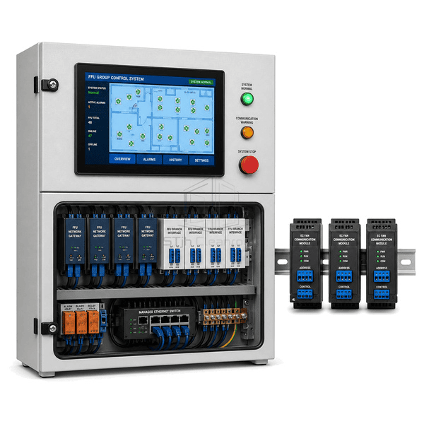
FFU Group Control System
A networked controller that supervises large banks of fan filter units, distributes speed setpoints and identifies individual FFU faults from one operator panel.
- Individual FFU Addressing
- Grouped Speed Commands
- Live Motor Feedback
- Fault Location by Unit
Produkteinführung
The FFU group control system connects individually addressed EC fan filter units through dedicated communication branches and industrial gateways. Operators can start, stop or change speed by room, zone or selected unit while receiving actual speed, current and fault status from each fan. Scheduled occupied and setback modes reduce unnecessary fan energy outside production periods. Branch segmentation keeps troubleshooting practical in large ceilings because a communication issue can be isolated without losing visibility of every cleanroom zone.
Key Features
Zone commands change multiple EC fan speed setpoints without editing every unit separately.
Returned speed, current and alarm states reveal stalled or disconnected FFUs quickly.
Segmented gateways support orderly expansion across multiple cleanroom ceiling grids.
Kunden Produktbedenken
A large FFU ceiling needs centralized control without making a single branch fault difficult to diagnose or service.
Technicians cannot identify which fan in a dense ceiling grid has failed.Addressed status feedback links each alarm to a room coordinate and FFU number.
Manual speed adjustment creates inconsistent airflow across adjacent zones.Group setpoints apply a coordinated command to every selected FFU branch.
Full-speed operation during idle hours wastes fan energy.Scheduled occupied and setback commands reduce speed when process demand is lower.
One communication fault can obscure a large number of ceiling units.Multiple isolated branches and gateways limit the affected section and preserve the remaining network.
Typische Anwendungen
Semiconductor cleanroom ceilingsPharmazeutische Filling SuitesElectronics assembly cleanroomsModular cleanroom installations
Technische Parameter
Typical construction for an FFU group control cabinet serving networked EC fan filter units is listed below.
| Core Material | Powder-coated steel cabinet with FR-4 control boards, isolated RS-485 interfaces and copper terminals |
|---|---|
| Panel Dicke | 180-350 mm cabinet depth |
| Effektive Breite | 500-1000 mm enclosure width |
| Maximale Länge | Up to 1800 mm enclosure height |
| Stahl facing Dicke | 1.2-1.8 mm powder-coated steel panels |
| Kerndichte | 7800-8050 kg/m³ for steel enclosure components |
| Thermische Leitfähigkeit | 45-60 W/(m·K) for steel structural parts |
| Oberfläche Finish | Light-gray textured powder coat with blue HMI bezel and labeled branch indicators |
| Gemeinsamer Typ | DIN-rail modular cabinet with segregated power and multi-branch Modbus terminal sections |
| Customisierung | Verfügbar je nach beabsichtigter Anwendung und Betriebsumgebung. |
Verfügbare Optionen
Modbus RTU or TCP gatewaysTouchscreen ceiling mapOccupied and setback schedulesRedundant communication branches
Planning a FFU Group Control System specification?
Senden Sie uns Ihre Abmessungen, Installationsbedingungen, Leistungsziele und gewünschte Oberflächenveredelung.