
 EnglishCurrent
 德语
德语 阿拉伯语
阿拉伯语 法语
法语 印尼语
印尼语 日语
日语 韩语
韩语 马来语
马来语 葡萄牙语
葡萄牙语 俄语
俄语 西班牙语
西班牙语 泰语
泰语 土耳其语
土耳其语 越南语
越南语

Cleanroom Testing and Validation Instruments
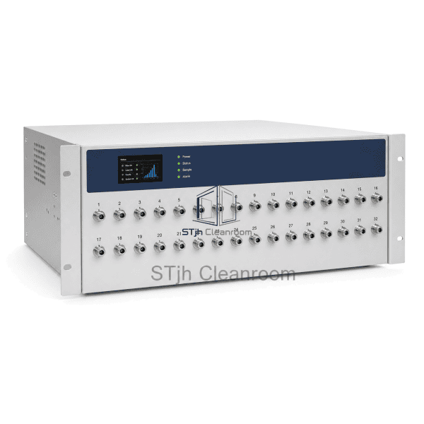
Multi-Channel Particle Monitoring System
A programmable aerosol manifold system that connects one particle counter to multiple cleanroom sampling locations for economical sequential monitoring.
- One counter polls multiple identified sampling points.
- Programmable purge and sample steps sequence each line.
- Point identities stay linked to monitoring software.
Product Introduction
This multi-channel particle monitoring system combines a precision valve manifold, clean sampling paths, sequence controller and compatible airborne particle counter. It automatically selects one location at a time, purges the active line and records the result against the correct point identifier. The architecture is intended for periodic trending across many locations where simultaneous continuous measurement is not required, reducing instrument count without losing a structured sampling plan.
Key Features
Programmable point order, purge duration and sample time create repeatable unattended monitoring cycles.
Bi-directional control allows the manifold and monitoring software to coordinate point status and timing.
Low-shedding internal flow paths minimize contamination contribution from the switching assembly.
Individual port identification keeps every particle result associated with the correct cleanroom location.
Modular tubing and communication options simplify phased expansion of the monitoring network.
Customer Product Concerns
Sequential monitoring must clear residue from long lines, preserve the identity of each location, and balance purge plus sample time against the required polling cycle.
Long tubing can delay the arrival of a representative sample from a distant point.Programmable purge intervals are assigned by line length so each point is cleared before its measurement begins.
Sequential sampling cannot detect simultaneous short excursions at every location.Use the manifold for periodic trend points and reserve dedicated remote counters for high-risk locations requiring continuous observation.
Incorrect valve mapping can associate data with the wrong room location.Numbered physical ports, locked software point names and commissioning verification establish a traceable channel map.
Particle loss in bends and excessive tubing may bias larger-size channels.Straight conductive tubing routes, controlled lengths and validated transport arrangements minimize avoidable deposition.
Typical Applications
Periodic multi-point particle trending in large cleanroomsElectronics and precision-manufacturing clean-zone monitoringNon-critical support rooms where sequential sampling is acceptableCentralized monitoring of distributed process enclosuresExpansion of an existing facility particle-monitoring network
Technical Parameters
The table defines representative cabinet, port, flow-path, and communication configurations for a multiport switching manifold, with selection based on point count, tubing layout, and particle-counter architecture.
| Core Material | Powder-coated steel or stainless-steel enclosure with chemically resistant internal valve manifold and clean sampling tubing |
|---|---|
| Panel Thickness | Typically 1.0–1.5 mm enclosure panel thickness |
| Effective Width | Approximately 430–600 mm according to port count and rack configuration |
| Maximum Length | Approximately 450–800 mm for the manifold enclosure; sampling runs may extend to 38100 mm when validated |
| Steel Facing Thickness | Typically 1.0–1.5 mm powder-coated or stainless steel |
| Core Density | Not applicable; the equipment enclosure has no insulation core (0 kg/m³) |
| Thermal Conductivity | Approximately 14–16 W/(m·K) for stainless steel or 45–60 W/(m·K) for carbon-steel enclosure sections |
| Surface Finish | Smooth light-gray powder coating or fine-brushed stainless steel with labeled stainless tube ports |
| Joint Type | Numbered compression-tube sampling ports with Ethernet or serial control interface |
| Customization | Available based on the intended application and operating environment. |
Available Options
8, 16, 24 or 32 sampling channelsRack-mount or wall-mount enclosureStainless-steel or powder-coated housingCompatible 28.3 L/min particle counterConductive sampling tubing and point probesFacility monitoring software integration
Planning a Multi-Channel Particle Monitoring System specification?
Send us your dimensions, installation conditions, performance targets and required surface finish.