
 EnglishCurrent
 德语
德语 阿拉伯语
阿拉伯语 法语
法语 印尼语
印尼语 日语
日语 韩语
韩语 马来语
马来语 葡萄牙语
葡萄牙语 俄语
俄语 西班牙语
西班牙语 泰语
泰语 土耳其语
土耳其语 越南语
越南语

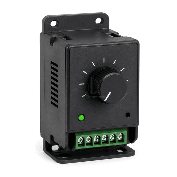
Cleanroom Equipment Spare Parts
FFU Speed Controller
A compact panel-mounted controller that gives operators direct, stepless airflow adjustment for compatible EC-motor fan filter units.
- Stepless Manual Adjustment
- EC Fan Signal Control
- Compact Panel Mounting
- Serviceable Screw Terminals
Product Introduction
The FFU speed controller provides a local setpoint for a compatible electronically commutated fan motor. Turning the front potentiometer varies the low-voltage command used by the motor electronics, allowing commissioning or maintenance personnel to trim airflow without replacing the FFU drive. The molded enclosure protects the control components, while mounting ears and a removable screw terminal block simplify installation near the fan housing or inside a control compartment. Signal range, terminal assignment and minimum-speed behavior must be matched to the existing motor or FFU control card.
Key Features
Low-voltage signal architecture is suited to EC fans that accept an analog speed command.
Front status indication provides a quick visual check that the control circuit is energized.
Screw terminals and external mounting tabs support straightforward replacement and servicing.
Customer Product Concerns
A replacement speed controller must produce the signal expected by the installed motor and fit the existing wiring and mounting arrangement.
The new controller uses a signal range that the existing EC motor cannot interpret correctly.The controller is selected to match the motor's specified analog command range and reference supply.
Airflow falls below the stable operating point at the lowest dial position.Minimum-speed behavior can be matched or preset to preserve the required lower airflow limit.
Different terminal assignments create wiring errors during field replacement.Terminal count, signal common, reference voltage and command output are verified against the original connection diagram.
The control cannot be secured near the FFU without modifying the housing.Mounting-tab geometry and enclosure orientation can be configured for the available service space.
Typical Applications
Single FFU airflow commissioningCleanroom ceiling fan filter unitsLaminar-flow workstation fansLocal EC fan maintenance control
Technical Parameters
Typical construction ranges for compact manual FFU speed controllers are shown below.
| Core Material | Flame-retardant PC/ABS enclosure with FR-4 control board and copper-alloy terminals |
|---|---|
| Panel Thickness | 35-70 mm nominal enclosure depth |
| Effective Width | 70-135 mm nominal mounting width |
| Maximum Length | Up to 160 mm overall length including mounting tabs |
| Steel Facing Thickness | 0.8-1.5 mm equivalent terminal-clamp and internal bracket thickness |
| Core Density | 1050-1250 kg/m³ for molded PC/ABS enclosure material |
| Thermal Conductivity | 0.18-0.25 W/(m·K) for molded enclosure material |
| Surface Finish | Fine-textured matte-black housing with white dial marks, green indicator and green terminal block |
| Joint Type | Six-position screw terminal connection with bolted external mounting tabs |
| Customization | Available based on the intended application and operating environment. |
Available Options
0-10 V or matched potentiometer interfaceMinimum-speed presetAlternative terminal assignmentCustom mounting-tab geometry
Planning a FFU Speed Controller specification?
Send us your dimensions, installation conditions, performance targets and required surface finish.