
 EnglishCurrent
 德语
德语 阿拉伯语
阿拉伯语 法语
法语 印尼语
印尼语 日语
日语 韩语
韩语 马来语
马来语 葡萄牙语
葡萄牙语 俄语
俄语 西班牙语
西班牙语 泰语
泰语 土耳其语
土耳其语 越南语
越南语

Cleanroom Testing and Validation Instruments
Airflow Visualization System
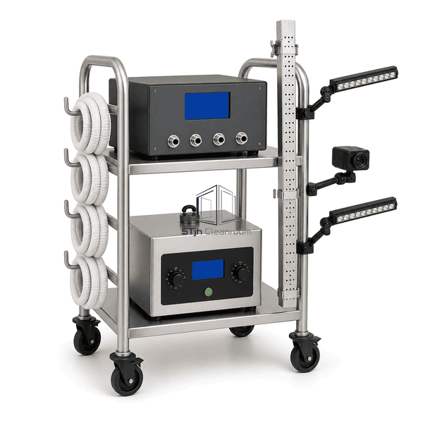
An integrated cleanroom smoke-study platform combining controllable tracer generation, distribution, illumination and synchronized video capture.
- Integrated smoke-study workflow.
- Multi-outlet controlled fog delivery.
- Coordinated illumination and capture.
Product Introduction
This modular system coordinates a high-purity fog source with a multi-outlet distribution manifold, adjustable LED lighting and camera interfaces for documented airflow studies. A central controller regulates tracer delivery while the wheeled equipment rack organizes hoses, power and recording connections. Interchangeable outlet bars support broad filter-face coverage or focused release around process equipment.
Key Features
Multi-outlet manifold supports uniform fog delivery across wide test zones.
Adjustable illumination increases contrast of fine airflow structures.
Central controls coordinate fog output and accessory operation.
Modular hoses and outlet bars adapt to rooms, isolators and filling lines.
Mobile rack keeps study components organized between test positions.
Customer Product Concerns
Complex aseptic airflow studies depend on coordinated tracer placement, lighting and recording; independently assembled components can create uneven coverage and inconsistent documentation.
Separate fog, lighting and camera equipment can be difficult to coordinate.The integrated rack organizes tracer delivery, illumination and recording interfaces in one workflow.
A single fog outlet may not cover a wide process zone evenly.Modular manifolds and outlet bars distribute tracer across the selected study width.
Fine fog structures may disappear against reflective equipment surfaces.Positionable neutral LED luminaires improve contrast for video capture.
Study configurations must be reproduced across operating scenarios.Central output controls and modular labeled connection points support repeatable setup geometry.
Typical Applications
Aseptic filling-line smoke studiesRABS and isolator airflow visualizationCleanroom dynamic airflow mappingHEPA coverage demonstrationsContainment and intervention studies
Technical Parameters
Representative integrated system construction is provided below; rack size, outlet geometry, camera count and hose lengths can be configured for the study protocol.
| Core Material | 316L stainless equipment rack, ultrasonic fog module, polymer hoses, LED luminaires and electronic controls |
|---|---|
| Panel Thickness | Typically 1.0-2.0 mm for rack and controller enclosure panels |
| Effective Width | Approximately 600-1000 mm across the mobile system rack |
| Maximum Length | Approximately 800-1400 mm for rack; distribution hoses available to 10000 mm |
| Steel Facing Thickness | Typically 1.0-1.5 mm for stainless equipment enclosures and manifold components |
| Core Density | Approximately 7950-8000 kg/m³ for 316L stainless components |
| Thermal Conductivity | Approximately 14-16 W/(m·K) for 316L stainless steel |
| Surface Finish | Brushed stainless rack with graphite controller, white hoses and black camera and lighting hardware |
| Joint Type | Quick-connect fog manifold, locking hose couplings and modular power and signal interfaces |
| Customization | Available based on the intended application and operating environment. |
Available Options
Single or multi-camera interfaceStraight or perforated fog barsAlternative manifold outlet countsHigh-output fog moduleBattery-backed controlsTransport cases for accessories
Planning a Airflow Visualization System specification?
Send us your dimensions, installation conditions, performance targets and required surface finish.