
 EnglishCurrent
 德语
德语 阿拉伯语
阿拉伯语 法语
法语 印尼语
印尼语 日语
日语 韩语
韩语 马来语
马来语 葡萄牙语
葡萄牙语 俄语
俄语 西班牙语
西班牙语 泰语
泰语 土耳其语
土耳其语 越南语
越南语

FFU and Terminal Air Purification Equipment
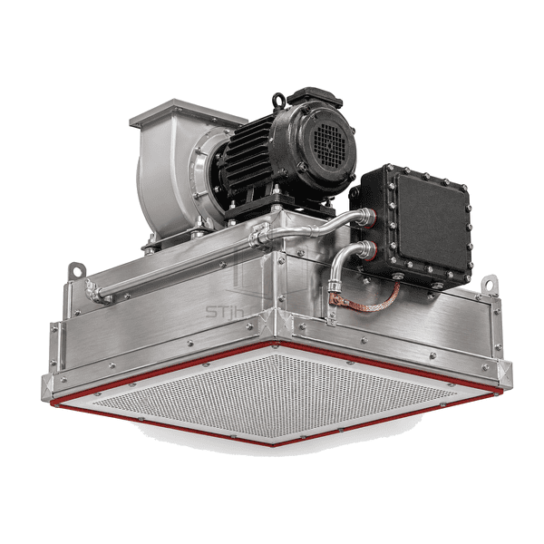
Explosion-Proof Fan Filter Unit
A hazardous-duty FFU built with a non-sparking blower, cast-metal motor enclosure, sealed electrical path and grounded filter frame for clean areas handling flammable vapors or dusts.
- Non-Sparking Blower Assembly
- Cast-Metal Motor Enclosure
- Sealed Junction Box and Conduit
- Bonded Grounding Path
Product Introduction
The explosion-proof fan filter unit isolates electrical and rotating ignition sources with a heavy cast-metal motor enclosure, bolted junction box, rigid conduit and sealed fittings. A non-sparking impeller moves air through the prefilter and final filter, while a dedicated bonding strap connects the casing and metal prefilter frame to ground. The reinforced stainless or rolled-steel plenum supports the heavier drive assembly and uses a baffled diffuser to distribute airflow. Electrical voltage, enclosure construction and hazardous-area suitability are selected to match the intended process environment.
Key Features
Bolted cast-metal junction hardware contains electrical terminations and connects through rigid sealed conduit.
A visible bonding strap links removable metal filter components to the grounded FFU casing.
The reinforced frame carries the concentrated motor load without distorting the filter seal or ceiling flange.
Customer Product Concerns
A hazardous clean area must control particles while preventing the fan, wiring and removable prefilter from introducing an avoidable ignition source.
An ordinary open motor and switch can expose arcing components to flammable vapor above the cleanroom ceiling.The motor, terminals and switching path are enclosed in bolted cast housings connected by rigid sealed conduit.
A metal prefilter can accumulate static charge when dry process air passes through its frame.A dedicated grounding clip and bonding lead connect the removable prefilter frame to the FFU enclosure.
A conventional steel impeller may create a spark if it contacts the inlet or housing after damage.The selected non-sparking impeller material and guarded clearances reduce metal-to-metal contact risk.
The heavy hazardous-duty motor can twist a light ceiling module and break filter compression.Reinforced mounting rails and corner brackets transfer the motor load around the sealed filter frame.
Typical Applications
Solvent-handling cleanroomsHazardous powder processing suitesBattery electrolyte preparation areasChemical dispensing enclosuresClean zones requiring sealed hazardous-duty electrical hardware
Technical Parameters
Typical construction ranges for a hazardous-duty explosion-proof fan filter unit are listed below.
| Core Material | Reinforced stainless or powder-coated steel plenum, non-sparking centrifugal impeller, cast-metal motor enclosure and micro-glass HEPA or ULPA filter |
|---|---|
| Panel Thickness | 450-550 mm overall module depth including the hazardous-duty motor assembly |
| Effective Width | 575-610 mm nominal module width |
| Maximum Length | Up to 1220 mm standard module length |
| Steel Facing Thickness | 1.2-2.0 mm reinforced stainless or powder-coated rolled-steel housing sheet |
| Core Density | Approximately 90-120 kg/m³ nominal compacted density of the final-filter pack used in the explosion-protected FFU assembly |
| Thermal Conductivity | Approximately 0.035-0.043 W/(m·K) for the dry final-filter pack used in the explosion-protected FFU assembly |
| Surface Finish | Brushed stainless steel or chemically resistant powder coating with grounded bare-metal bonding points |
| Joint Type | Reinforced ceiling flange with bonded perimeter gasket and room-side gel-seal or compression-seal filter interface |
| Customization | Available based on the intended application and operating environment. |
Available Options
120, 208-240 or 277 V motor configurationStainless or powder-coated reinforced housingGrounded room-side replaceable HEPA or ULPA filterHazard-specific conduit, junction and grounding arrangement
Planning a Explosion-Proof Fan Filter Unit specification?
Send us your dimensions, installation conditions, performance targets and required surface finish.