 EnglishCurrent
 德语
德语 阿拉伯语
阿拉伯语 法语
法语 印尼语
印尼语 日语
日语 韩语
韩语 马来语
马来语 葡萄牙语
葡萄牙语 俄语
俄语 西班牙语
西班牙语 泰语
泰语 土耳其语
土耳其语 越南语
越南语

FFU and Terminal Air Purification Equipment
FFU Ceiling Grid System
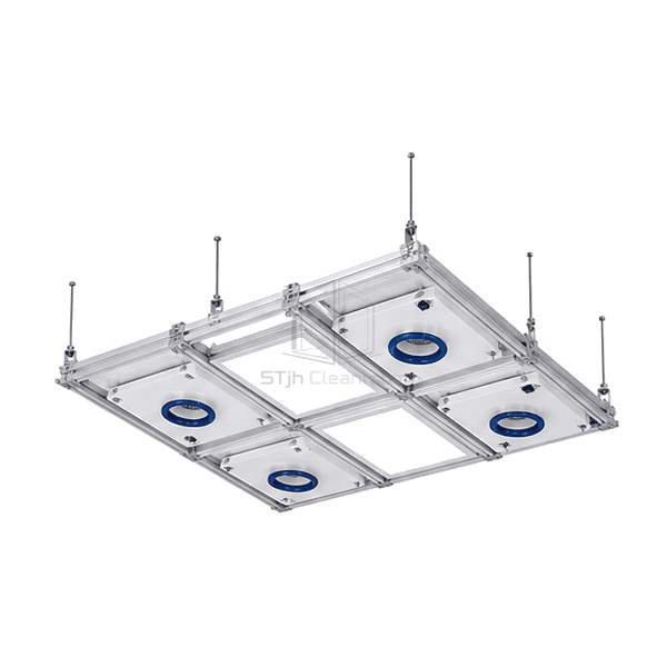
A sealed modular T-grid structure that coordinates FFUs, lights, blank panels and service modules while transferring their loads to wall supports or suspension rods.
- Modular FFU Bays
- Factory-Applied Gaskets
- Integrated Utility Support
- Replaceable Grid Components
Product Introduction
The FFU ceiling grid system uses interlocking aluminium or stainless profiles to create repeatable bays for fan filter units, LED panels, blank tiles and utility penetrations. Factory-applied closed-cell gaskets seal the underside contact line, while splice clips, corner keys and hanger points maintain alignment across the ceiling field. Standard module pitches accept common FFU formats, and partial bays can be fitted with sealed infill panels. The system provides a coordinated structural and sealing interface; it does not replace the independent building structure required to carry the calculated ceiling loads.
Key Features
Continuous closed-cell gasketing limits bypass paths between the grid and drop-in components.
Interlocking splice hardware keeps exposed ceiling lines straight without bulky room-side fasteners.
Dedicated suspension and perimeter members separate component loading from cleanroom wall panels.
Customer Product Concerns
A dense FFU ceiling must remain sealed and visually aligned while carrying many service modules and still permitting future reconfiguration.
Small dimensional errors accumulate across a large ceiling and prevent FFUs from dropping into their bays.Factory-sized main runners, cross tees and positive splice keys hold a repeatable module pitch.
Air leaks through hard contacts between filters, lights and bare T-bar flanges.A continuous closed-cell gasket creates a compressible seal beneath each drop-in component.
Replacing one FFU requires dismantling neighbouring ceiling sections.Independent bays and removable hold-down hardware allow a single module to be lifted or lowered.
Uncoordinated lights and service penetrations overload isolated grid members.Load paths, suspension points and utility bays are arranged within one ceiling support layout.
Typical Applications
Semiconductor ballroom ceilingsModular pharmaceutical cleanroomsMedical-device production suitesAerospace assembly clean zonesResearch laboratory cleanrooms
Technical Parameters
Typical material and module ranges for a gasketed FFU ceiling grid system are shown below.
| Core Material | 6063-T5 aluminium T-grid profiles with steel suspension rods and closed-cell PE or EPDM gaskets |
|---|---|
| Panel Thickness | 38-75 mm nominal grid web depth |
| Effective Width | 600-1200 mm standard module pitch with metric or imperial bay layouts |
| Maximum Length | Up to 6000 mm continuous primary runner length before a mechanical splice |
| Steel Facing Thickness | 1.0-2.0 mm galvanized steel support plates or stainless component trays where fitted |
| Core Density | 30-80 kg/m³ nominal density of the closed-cell perimeter gasket |
| Thermal Conductivity | 0.035-0.060 W/(m·K) for the closed-cell grid sealing gasket |
| Surface Finish | Cleanroom-white powder-coated aluminium, clear anodized aluminium or brushed 304 stainless steel |
| Joint Type | Interlocking T-bar splice clips and corner keys with gasketed drop-in module seats |
| Customization | Available based on the intended application and operating environment. |
Available Options
600 × 600 or 600 × 1200 mm baysWall-supported or rod-suspended layoutPowder-coated aluminium or stainless finishFFU, light, blank panel and utility modules
Planning a FFU Ceiling Grid System specification?
Send us your dimensions, installation conditions, performance targets and required surface finish.