 EnglishCurrent
 德语
德语 阿拉伯语
阿拉伯语 法语
法语 印尼语
印尼语 日语
日语 韩语
韩语 马来语
马来语 葡萄牙语
葡萄牙语 俄语
俄语 西班牙语
西班牙语 泰语
泰语 土耳其语
土耳其语 越南语
越南语

FFU and Terminal Air Purification Equipment
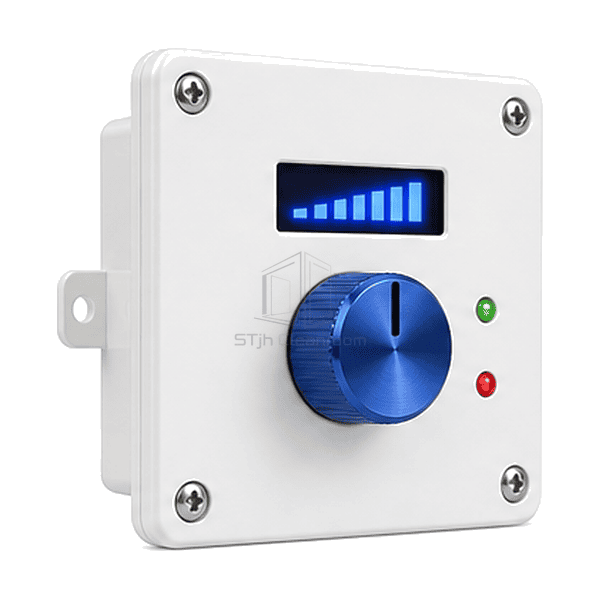
EC FFU Speed Controller
A local low-voltage controller that adjusts one EC fan filter unit through an isolated 0–10 V or PWM command and displays its operating setpoint.
- Local Airflow Setpoint
- Isolated 0-10 V Output
- Remote Enable Input
- Compact Wall Mount
Product Introduction
The EC FFU speed controller provides a simple room-side interface for one fan filter unit or a small matched pair. A sealed rotary knob sets the airflow command, and an optional digital display shows percentage, voltage or fan feedback. Galvanic isolation protects the low-voltage signal from field wiring noise, while a remote enable input allows a door interlock, occupancy relay or supervisory panel to place the FFU into standby. The controller regulates the EC motor command only; mains isolation and motor protection remain within the FFU electrical assembly.
Key Features
The isolated analogue output reduces ground-loop errors on long control cables.
Remote enable contacts permit standby operation from an external cleanroom sequence.
A removable terminal plug speeds replacement without disturbing fixed field conductors.
Customer Product Concerns
A standalone EC FFU needs stable speed adjustment without exposing mains wiring or forcing operators to reach above the cleanroom ceiling.
The factory trim potentiometer is inaccessible after the FFU is installed above the ceiling.A room-side rotary control places the setpoint at a convenient operating location.
Voltage drop and electrical noise make the fan speed drift on a long signal cable.An isolated 0-10 V output and referenced common improve command stability.
The fan must enter standby when a process tool stops, but its speed setting should be retained.A separate enable input disables the output without moving the setpoint knob.
Replacing a failed controller requires every conductor to be removed individually.A keyed pluggable terminal block disconnects the complete low-voltage harness as one assembly.
Typical Applications
Single EC fan filter unitsClean benches and mini-environmentsIndependent ceiling FFU zonesEquipment fan filter modulesLaboratory clean-air stations
Technical Parameters
Representative physical ranges for a local EC FFU speed controller are listed below.
| Core Material | Microcontroller board with isolated 0-10 V or PWM output, sealed potentiometer and optional digital display |
|---|---|
| Panel Thickness | 45-90 mm installed controller depth |
| Effective Width | 86-150 mm faceplate width |
| Maximum Length | Up to 200 mm enclosure height |
| Steel Facing Thickness | 0.8-1.0 mm stainless or powder-coated steel mounting plate when specified |
| Core Density | Approximately 1800-1900 kg/m³ nominal density of the FR-4 substrate used in the EC speed controller |
| Thermal Conductivity | Approximately 0.25-0.40 W/(m·K) through the compact FR-4 board in the EC speed controller |
| Surface Finish | White flame-retardant polymer or cleanroom-white powder-coated metal faceplate with blue control knob |
| Joint Type | Flush or surface wall mount with keyed pluggable low-voltage terminals or RJ-style control connector |
| Customization | Available based on the intended application and operating environment. |
Available Options
Rotary-only or digital display version0-10 V, PWM or EC motor-specific outputRemote enable and fault inputFlush wall plate or surface enclosure
Planning a EC FFU Speed Controller specification?
Send us your dimensions, installation conditions, performance targets and required surface finish.