
 EnglishCurrent
 德语
德语 阿拉伯语
阿拉伯语 法语
法语 印尼语
印尼语 日语
日语 韩语
韩语 马来语
马来语 葡萄牙语
葡萄牙语 俄语
俄语 西班牙语
西班牙语 泰语
泰语 土耳其语
土耳其语 越南语
越南语

Cleanroom Utility Systems
Compressed Air Receiver
A space-efficient 500 L vertical receiver that buffers compressed-air demand, limits rapid pressure swings and provides a low point for condensate collection.
- 500 L vertical buffer volume
- 11 bar working-pressure class
- Gauge, relief valve and bottom drain
Product Introduction
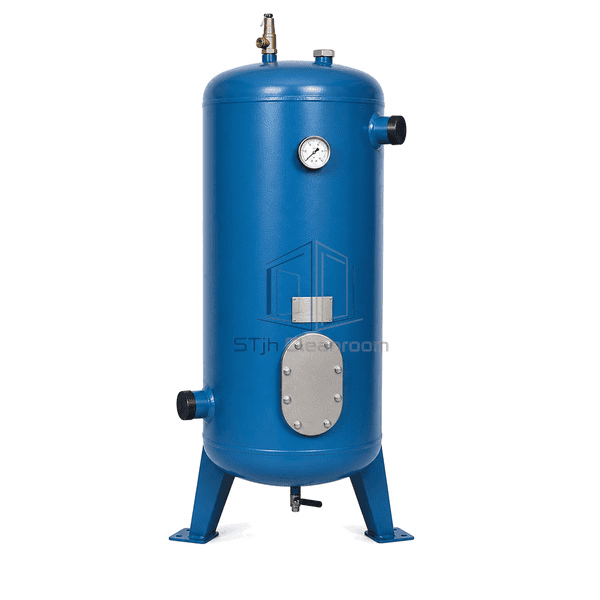
The Compressed Air Receiver is a standalone welded carbon-steel pressure vessel placed between air generation and the distribution network to provide temporary storage. The selected vertical 500 L configuration uses dished ends, a cylindrical shell and three welded support legs to minimize floor area while keeping the drain and inspection opening accessible. Stored air helps absorb short demand peaks and slows pressure changes while compressor controls respond. The vessel is finished in industrial azure-blue powder coating and carries separate connections for inlet, outlet, pressure indication, pressure relief and condensate discharge. It does not compress, dry, filter or sterilize air, so air treatment and final quality monitoring remain separate system functions.
Key Features
Welded carbon-steel shell and formed heads provide a conventional industrial pressure-vessel structure
Two separated side connections support lower inlet and upper outlet routing through the receiver volume
A clearly visible analog pressure gauge gives a direct local indication of receiver pressure
A spring-loaded relief valve is mounted directly at the top without an isolating valve in between
The lowest-point manual drain supports removal of collected water and compressor carryover
A bolted oval inspection opening provides access for internal examination when the vessel is isolated
Three reinforced legs with drilled footplates create a stable, anchorable installation base
Customer Product Concerns
A compressed-air plant can have adequate average compressor capacity yet still experience short pressure dips, frequent compressor cycling and liquid accumulation when storage is undersized or poorly arranged.
Short bursts of pneumatic demand can pull system pressure down before compressor output increasesUse the 500 L receiver as local buffer volume so stored air supports the transient demand while the compressor control system responds.
Limited storage can cause a fixed-speed compressor to load, unload or start too frequentlyAdd receiver volume sized to the demand profile to lengthen control intervals and reduce avoidable rapid cycling.
Cooling inside the vessel can collect water and compressor carryover at the lowest pointRoute the bottom connection to an accessible manual or automatic condensate drain and maintain an appropriate draining schedule.
A horizontal tank may consume valuable service-room floor lengthSelect the vertical three-leg layout to place 500 L of storage within an approximately 600 mm vessel diameter.
Pressure indication, relief protection and internal access can become obstructed after installationKeep the front gauge, top relief valve, lower inspection cover and drain fully accessible in the final piping and foundation layout.
Typical Applications
Central cleanroom utility-air stationsPharmaceutical packaging and pneumatic-control networksMedical-device assembly compressed-air systemsElectronics production and instrument-air distributionFood and beverage processing utility airIntermittent pneumatic equipment with short peak-demand events
Technical Parameters
The selected catalogue-scale configuration is a 500 L vertical compressed-air receiver rated for a maximum working pressure of 11 bar. Its representative envelope is approximately 2100 mm high by 600 mm in vessel diameter. The visual configuration uses an azure-blue powder-coated carbon-steel shell, three welded legs, two main side air connections, a front pressure gauge, one top relief valve, one lower oval inspection opening and one bottom manual drain. Receiver capacity, connection sizes, wall thickness, relief capacity and drain arrangement remain selectable for the actual flow, pressure, temperature and condensate load.
| Core Material | Welded carbon-steel pressure-vessel shell with formed carbon-steel heads and reinforced carbon-steel support legs |
|---|---|
| Panel Thickness | Pressure-vessel shell plate typically 5-8 mm for this size class; final wall selected for the design conditions |
| Effective Width | 600 mm vessel diameter for the selected 500 L vertical configuration |
| Maximum Length | Approximately 2100 mm overall height for the selected 500 L receiver |
| Steel Facing Thickness | No separate facing; the load-bearing carbon-steel shell is typically 5-8 mm |
| Core Density | Carbon steel approximately 7850 kg/m³ |
| Thermal Conductivity | Carbon steel approximately 48 W/(m·K) at 20°C |
| Surface Finish | Azure-blue RAL 5009 exterior powder coating with black valve handles and natural-metal gauge, relief valve, inspection cover and nameplate |
| Joint Type | Two opposed threaded G 1¼ main air sockets with dedicated threaded gauge, relief and lowest-point drain bosses |
| Customization | Available based on the intended application and operating environment. |
Available Options
Alternative receiver volumes for calculated general or dedicated storageHigher working-pressure configurationsHot-dip galvanized internal and external finishAlternative powder-coat colorThreaded or flanged inlet and outlet connectionsElectronic zero-loss or timed automatic condensate drainAlternative pressure-gauge range and dial sizeRelief-valve capacity matched to connected compressor flowHorizontal receiver arrangement where height is restricted
Planning a Compressed Air Receiver specification?
Send us your dimensions, installation conditions, performance targets and required surface finish.