
 English
 الألمانية
 العربيةالحالي
 الفرنسية
 الإندونيسية
 اليابانية
 الكورية
 اللغة الملاوية
 البرتغالية
 الروسية
 الإسبانية
 التايلاندية
 اللغة التركية
 اللغة الفيتنامية

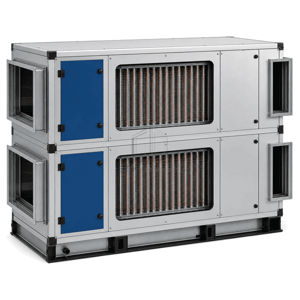
معدات تهوية وتكييف ومعالجة الهواء في الغرف النظيفة
وحدة استرداد الطاقة الحرارية
A finned copper-tube recovery module that bridges adjacent supply and exhaust sections with individually charged circuits and an integral sealed divider.
- Hermetically Sealed Copper Circuits
- Integral Air-Stream Divider
- Up to Eight Tube Rows
- Serviceable Finned Faces
مقدمة المنتج
The heat-pipe energy recovery unit extends individually charged copper circuits through two finned sections located in adjacent supply and exhaust ducts. Working fluid evaporates in the warmer half, travels through each sealed circuit and condenses in the cooler half before returning. An integral metal partition is expanded and sealed around every tube penetration so the two duct sections remain physically divided. Circuit geometry can be arranged for side-by-side horizontal air paths or one stream above the other, with the charge and return path selected for equal seasonal recovery or a preferred heating or cooling duty.
الخصائص الرئيسية
Copper tube penetrations are mechanically expanded into the integral divider to preserve separation between the two air paths.
Selections up to eight tube rows and multiple aluminum or copper fin densities match available face area and pressure-drop limits.
Accessible fin faces, protective coating options and a dedicated drain section simplify cleaning and wet-side maintenance.
مخاوف المنتج للعملاء
Heat-pipe recovery depends on the physical relationship between the two ducts, even airflow across the finned faces and suitable drainage and frost protection at the cold section.
Supply and exhaust ducts are often stacked vertically rather than aligned side by side.The divided module can be configured for adjacent horizontal paths or an over-under arrangement with a circuit layout suited to the installed orientation.
High face velocity creates excessive pressure drop and leaves the downstream fan with insufficient reserve.The coil face width, height, row count and fin spacing are selected together to keep velocity and resistance within the ventilation duty.
Wet exhaust deposits and corrosive residue reduce heat transfer at the leading fin edges.Wider fin spacing, accessible faces and an application-compatible fin coating preserve cleanable surface area in demanding exhaust service.
Condensate or frost restricts the cold fin section during low outdoor-temperature operation.A correctly sloped drain pan combined with bypass or preheat control keeps liquid and ice from progressively blocking the face.
تطبيقات نموذجية
Laboratory exhaust and outdoor-air heat recoveryHospital and healthcare ventilationClean manufacturing make-up airData-center indirect cooling systemsIndustrial process ventilation with separated air streams
المعلمات الفنية
Representative construction ranges for a divided HVAC heat-pipe recovery module are shown below.
| المواد الأساسية | Individually charged copper loop heat-pipe circuits with phase-change working fluid and aluminum fins |
|---|---|
| سمك اللوحة | Approximately 230 mm finned core depth in the airflow direction for a typical six-row module |
| العرض الفعال | 500–3000 mm nominal finned-face width across common modular selections |
| الحد الأقصى الطول | Up to 5080 mm active copper-tube length across the module face |
| الصلب يواجه سمك | Approximately 1.5 mm minimum galvanized or stainless frame and air-stream divider |
| الكثافة الأساسية | 8960 kg/m³ copper tube material |
| الموصلية الحرارية | Approximately 385 W/(m·K) for the copper tube wall |
| إنهاء السطح | Aluminum fins on copper tubes with optional epoxy or hydrophilic coating and powder-coated casing |
| نوع المشترك | Hermetically sealed loop circuits passing through an expanded tube-to-divider joint in a flanged frame |
| التخصيص | متوفر على أساس التطبيق المقصود وبيئة التشغيل. |
الخيارات المتاحة
Side-by-side or over-under air-stream arrangementEqual seasonal, heating-optimized or cooling-optimized circuit layoutFour to eight tube rows with aluminum or copper fin selectionsProtective fin coating, bypass damper and condensate drain pan
Planning a Heat-Pipe Energy Recovery Unit specification?
أرسل لنا الأبعاد الخاصة بك، شروط التثبيت، أهداف الأداء والتشطيب السطحي المطلوب.