
 English
 الألمانية
 العربيةالحالي
 الفرنسية
 الإندونيسية
 اليابانية
 الكورية
 اللغة الملاوية
 البرتغالية
 الروسية
 الإسبانية
 التايلاندية
 اللغة التركية
 اللغة الفيتنامية

أنظمة المرافق الغرف النظيفة
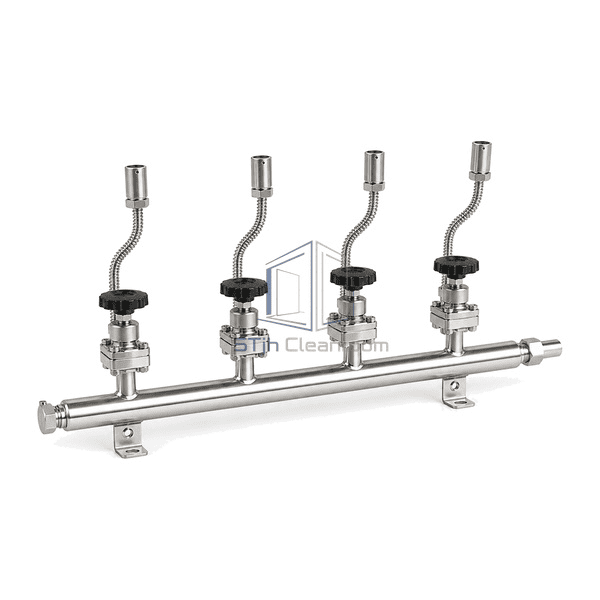
Gas manifold
A wall-mounted four-inlet 316L stainless gas manifold that combines compatible high-purity cylinder sources through separately isolated pigtails into one common supply connection for downstream pressure control.
- Four independently isolated cylinder-source connections
- Compact 316L header with one common process outlet
- Gas-specific pigtails, check valves and purge provisions available
مقدمة المنتج
The Gas Manifold is a source-inlet header for connecting multiple compatible gas cylinders to one downstream pressure-control or changeover assembly. The selected catalogue configuration uses one horizontal 316L stainless header on two rigid wall brackets, four equally spaced inlet branches, four diaphragm isolation valves, four flexible metal pigtails with cylinder connectors, and one common outlet at the right end. Each source can be isolated before a cylinder is disconnected, while optional non-return and vent components can limit reverse flow and provide a defined route for clearing an inlet leg. This product contains no pressure regulator, gauge, automatic selector, controller, distribution sticks, cabinet or process-tool outlets; its function is to collect source gas rather than reduce pressure or divide regulated gas among users.
الخصائص الرئيسية
A dedicated diaphragm isolation valve on every inlet allows one cylinder connection to be secured independently
Compact branch spacing keeps pigtail routing orderly and makes each source position easy to identify
A continuous stainless header minimizes unnecessary joints between the source legs and common outlet
Optional inlet check valves reduce the possibility of reverse flow between connected source positions
Optional branch vent valves provide a controlled path for clearing trapped gas before a pigtail is opened
Rigid wall brackets support the header so cylinder loads are not transferred to downstream tubing
Gas-specific cylinder connectors and pigtail materials can be selected without changing the four-inlet collection layout
An open component arrangement gives technicians direct access for inspection and planned valve or pigtail replacement
Modular extension sections can increase source capacity where the selected manifold family permits expansion
مخاوف المنتج للعملاء
A cylinder-source manifold must preserve gas identity and inlet cleanliness while preventing one cylinder change from disturbing the common supply or imposing mechanical load on the permanent header.
Several cylinders connected through loose tees and unsupported hoses create confusing flow paths and unnecessary leak pointsUse one fixed header with four clearly spaced, permanently identified source legs and a single defined common outlet.
Disconnecting one depleted cylinder can expose the shared header to ambient air or release trapped source gasIsolate the individual inlet and use the specified branch vent or purge sequence before opening its cylinder connector.
Pressure from one live cylinder can migrate toward another inlet when source legs lack reverse-flow protectionSelect gas-compatible check valves for the inlet legs and verify their orientation as part of the installed flow path.
A pigtail with the wrong connector or material can be attached to an incompatible gas serviceMatch every pigtail, cylinder connector, seal and valve material to the named gas and keep permanent source-position identification.
Cylinder movement or short unsupported hoses can transmit bending force into the manifold tubeAnchor both wall brackets independently and choose pigtail length and restraint positions that leave a controlled service loop.
A bare collection header may be mistaken for a complete pressure-control or automatic-changeover stationPlace the required regulator, relief, monitoring and changeover functions in the correctly specified downstream subsystem rather than assigning them to the manifold.
تطبيقات نموذجية
High-purity nitrogen, argon or helium cylinder banks for clean manufacturing utilitiesSemiconductor and electronics support areas feeding a separate gas panel or automatic changeoverAnalytical laboratories that require a centralized multi-cylinder instrument-gas sourcePharmaceutical and biotechnology utility rooms using compatible process or calibration gasesResearch and pilot facilities with planned cylinder-bank expansionSpecialty-gas source stations where open manifold installation is permitted by the gas hazard assessment
المعلمات الفنية
The selected catalogue basis follows GCE Druva high-purity four-inlet extension-header architecture: one 316L stainless collection tube with four inlet positions, individual diaphragm isolation valves, optional non-return and vent functions, and a single outlet to a separate manifold control stage. A representative current four-inlet L030 envelope is approximately 1226 mm long, 110 mm deep and 220 mm high. The reference tubing is 316L stainless with 1/4 in. outside diameter and approximately 0.9 mm wall thickness, cleaned for high-purity gas service. Cylinder connector standard, pigtail construction, valve trim, check-valve arrangement, purge method, pressure class, flow capacity and gas compatibility remain selected for the actual source gas and facility design.
| المواد الأساسية | AISI 316L stainless collection tubing, diaphragm-valve bodies, pigtails and gas-wetted connection hardware |
|---|---|
| سمك اللوحة | 2.0 mm nominal formed stainless wall-bracket and support-rail thickness |
| العرض الفعال | 110 mm representative installed depth across the selected four-inlet valve and connection plane |
| الحد الأقصى الطول | 1226 mm representative overall header length for the selected compact four-inlet configuration |
| الصلب يواجه سمك | 0.9 mm nominal wall thickness for the representative 1/4 in. 316L collection tubing |
| الكثافة الأساسية | Approximately 8000 kg/m³ representative density for AISI 316L stainless gas-wetted components |
| الموصلية الحرارية | Approximately 15 W/(m·K) near 20°C for representative AISI 316L components |
| إنهاء السطح | Natural-silver stainless finish with cleaned gas-wetted tubing, typically Ra ≤ 0.8 µm internally and Ra ≤ 1.0 µm externally for the selected header class |
| نوع المشترك | Welded 316L header branches with gas-specific cylinder pigtail connections, individual diaphragm isolation valves and one common downstream outlet |
| التخصيص | متوفر على أساس التطبيق المقصود وبيئة التشغيل. |
الخيارات المتاحة
Two-, three- or four-inlet source-header sectionsLeft-hand or right-hand common outlet orientationFlexible stainless hose or coiled-tube pigtailsGas-specific CGA, DIN, BS or DISS cylinder connectorsInlet check valves, vent valves or combined check-and-vent assembliesLocal contact gauge or pressure-transmitter source monitoring316L stainless or selected compatible alloy wetted constructionPigtail length and branch spacing for cylinders or bundlesExpansion connection for a second compatible header section
Planning a Gas Manifold specification?
أرسل لنا الأبعاد الخاصة بك، شروط التثبيت، أهداف الأداء والتشطيب السطحي المطلوب.