
 日本語
日本語 ドイツ人。
ドイツ人。 アラビア語:アラビア語
 フランス語で
 インドネシア語
 日本語で。流れ
 韓国語
韓国語 マレー語
マレー語 ポルトガル語
 ロシア語
ロシア語 スペイン語
スペイン語 タイ語
タイ語 トルコ語
トルコ語 ベトナム語
ベトナム語

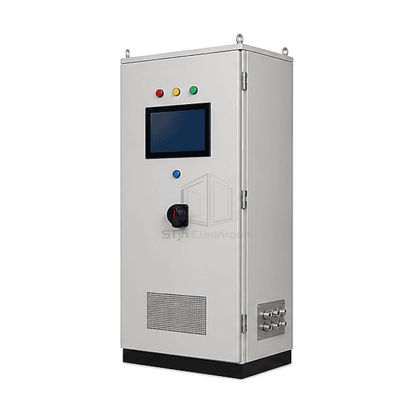
FFU およびターミナル空気浄化装置
FFU 中央制御システム
A floor-standing control cabinet that supervises multiple FFU zones through an industrial HMI, protected power distribution and building-network communication.
- Multi-Zone HMI Control
- Central Alarm Overview
- Operating Data Logging
- BACnet or Modbus Interface
商品紹介
The FFU central control system consolidates cleanroom fan commands, feedback and alarms in a lockable electrical cabinet. An industrial touchscreen presents zone status, airflow or speed setpoints and maintenance warnings, while internal PLC, power supplies, circuit protection and network repeaters distribute commands to field-connected EC fan filter units. The architecture can place routine room operation on the HMI and pass selected points to the building management system. Separate power and communication terminals simplify commissioning and isolate a field wiring fault from the supervisory electronics.
主要な特徴
PLC-based sequences can apply occupied, standby and recovery setpoints to different cleanroom areas.
Logged fan hours, alarm events and selected environmental points support maintenance planning.
Isolated BACnet or Modbus communication exchanges approved status and command points with the BMS.
お客様の製品に関する懸念事項
A large FFU installation becomes difficult to operate when individual units lack common setpoints, fault visibility and a controlled interface to the building system.
Operators walk through multiple rooms to change hundreds of local fan settings.The central HMI applies commands to defined FFU zones from one supervised interface.
A failed fan remains unnoticed until particle control is affected.Motor feedback and communication alarms identify the affected address and zone promptly.
Night operation consumes full fan power even when contamination loads are low.Scheduled occupied and standby modes reduce selected EC fan setpoints without shutting down monitoring.
Direct BMS commands can conflict with local cleanroom operating sequences.A defined gateway exposes selected points while the PLC retains interlocks and command priorities.
典型的な用途
Large semiconductor FFU ceilingsMulti-room pharmaceutical facilitiesBattery dry-room clean zonesDisplay and optics manufacturingCentral cleanroom operations centres
技術的なパラメータ
Representative enclosure and electronics ranges for an FFU central control system are listed below.
| コア材料 | Industrial PLC, touchscreen HMI, 24 VDC power supplies, protected distribution and isolated RS-485/Ethernet gateways |
|---|---|
| パネルの厚さ | 180-300 mm control-cabinet depth |
| 有効幅 | 600-1000 mm nominal cabinet width |
| 最大長さ | Up to 1800 mm cabinet height for expanded power and communication sections |
| 鋼鉄の厚さを直面する | 1.5-2.0 mm powder-coated steel enclosure and hinged front door |
| コア密度 | Approximately 1800-1900 kg/m³ nominal density of the FR-4 substrate used in the central control board |
| 熱伝導率 | Approximately 0.25-0.40 W/(m·K) through the FR-4 substrate inside the FFU central controller |
| 表面仕上げ | Light-grey or cleanroom-white epoxy-polyester powder-coated cabinet with sealed HMI bezel |
| ジョイントタイプ | Gasketed hinged door, DIN-rail terminal blocks, separated gland plates and pluggable field connectors |
| カスタマイズ | 意図したアプリケーションと動作環境に基づいて利用できます。 |
利用可能なオプション
Wall-mount or floor-standing cabinetBACnet MS/TP, Modbus RTU or Ethernet gatewayDifferential pressure and temperature inputsRemote web dashboard and event logging
Planning a FFU Central Control System specification?
寸法、設置条件、性能目標、必要な表面仕上げをお送りください。