
 İngilizce
 Almanca
 Arapça
 Fransızca
 Endonezya dilinde
 Japonca
 Korece
 Malay dilinde
 Portekizce
 Rusça
Rusça İspanyolca
 Taylandca
 TürkçeCurrent
 Vietnamca

Temiz Oda Hizmet Sistemi
Gaz Kontrol Panel
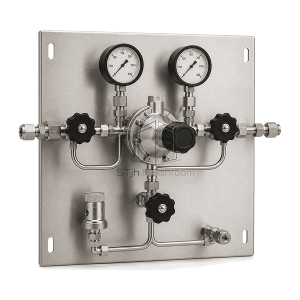
A wall-mounted single-source panel that reduces cylinder or bundle pressure, displays inlet and delivery conditions, isolates both sides of the regulator, and provides an external inert-purge path for controlled line preparation and source changeout.
- Single-bank primary pressure reduction on an open serviceable panel
- Separate high-pressure, low-pressure and external-purge isolation
- Upstream and downstream gauges with configurable relief and vent routing
Ürün tanıtımı
The Gas Control Panel is the primary pressure-control station between one compressed-gas source bank and the downstream distribution line. The selected catalogue configuration mounts one single-stage diaphragm pressure regulator, two mechanical pressure gauges, three manual diaphragm shutoff valves, one compact relief device, and clearly separated process and purge tubing on one brushed stainless wall plate. Source gas enters the high-pressure side, passes through controlled isolation and regulation, and leaves at the selected delivery pressure. A separate inert-gas connection permits the isolated upstream volume to be purged before a source connection is opened. The exposed arrangement keeps instruments and service joints visible without enclosing a cylinder. It is not ID 1936's exhausted automated specialty-gas cabinet, ID 1937's passive cylinder storage cabinet, ID 1939's enclosed multi-branch valve manifold box, or an automatic two-bank changeover system.
Ana Özellikler
A diaphragm regulator limits wetted dead volume and avoids a piston sliding seal in the selected high-purity flow path
Separate inlet and outlet gauges let operators distinguish remaining source pressure from regulated delivery pressure
Independent high-pressure and low-pressure isolation valves support controlled startup, shutdown, regulator service and line isolation
An external purge inlet and dedicated purge valve allow the trapped high-pressure section to be displaced with a compatible inert gas
A configurable relief or captured-vent connection provides a defined route for regulator venting and abnormal downstream pressure
A compact open backplate keeps valves, gauges and compression or face-seal joints accessible for inspection and maintenance
Gas-specific regulator range, seals, cleaning, tubing size and connection style can be selected without changing the basic panel architecture
Müşteri Ürün Sorunları
Stable gas delivery depends on matching the regulator, purge arrangement, materials and pressure ratings to the actual gas and operating range rather than treating every panel as interchangeable.
A regulator selected only by maximum inlet pressure can deliver excessive droop or poor adjustment resolution at the required flowSize the regulator flow coefficient and outlet spring range around the normal delivery pressure and expected flow, then verify the published flow curve for the selected gas.
Falling cylinder pressure can shift the outlet of a single-stage regulator and disturb a pressure-sensitive downstream processUse a two-stage regulator option or add a downstream point-of-use regulator when the allowable supply-pressure effect is tighter than a single stage can maintain.
Opening a depleted source connection can admit air and moisture to a clean gas line or release residual process gasIsolate both process sides and use the dedicated compatible inert-purge path to clear the trapped high-pressure volume before disconnection.
A vent or relief outlet left in the occupied space can create an uncontrolled discharge pathSpecify captured regulator vent and relief connections where required and route them to the facility's designated safe handling system.
Incompatible seat, diaphragm or seal materials can contaminate the stream or degrade in reactive gas serviceSelect wetted alloy, diaphragm, seat and seal materials against the named gas, pressure, temperature and required purity before fabrication.
Unclear valve positions make startup and source-change procedures prone to incorrect sequencingUse a consistent flow layout, permanent port identification and an operating sequence that verifies isolation, purge and pressure conditions at each step.
Tipik uygulamalar
Centralized high-purity gas supply for clean laboratories and analytical instrumentsSemiconductor and electronics utility-gas pressure reduction upstream of process toolsPharmaceutical and biotechnology equipment supplied with nitrogen, argon or other compatible gasesControlled purge-gas supply for clean process skids, isolators and gloveboxesCalibration, carrier and detector-gas distribution from a cylinder or small source bankResearch and pilot facilities requiring a visible serviceable wall-mounted gas pressure station
Teknik parametreler
The catalogue basis is a single-bank manual gas control panel in the Swagelok SGP and Linde HiQ REDLINE S 203 class. It uses one diaphragm pressure regulator, upstream and downstream gauges, high- and low-pressure process isolation, an external purge valve, a relief or captured-vent path and a stainless wall plate. Published commercial configurations cover primary pressures up to 230-300 bar and selectable outlet ranges; these are configuration limits rather than a universal operating point. The illustrated compact basis uses a representative 277 mm overall width and 254 mm panel height, while the regulator range, tubing size, gas-specific connections, seals, cleaning level and discharge routing are selected for the actual service.
| Temel malzemeler | AISI 316L stainless wetted regulator, diaphragm valves and seamless tubing on a brushed stainless-steel mounting plate |
|---|---|
| Panel kalınlığı | 2.0 mm nominal stainless mounting-plate thickness for the selected compact wall-panel configuration |
| Effective Width (Etkili Genişlik) | 277 mm representative overall width for the selected single-source pressure-control arrangement |
| Maksimum uzunluk | 254 mm representative panel height before external source, purge, vent and delivery tubing |
| Çelik yüz yüze kalınlığı | 0 mm separate facing sheet; the assembly uses one solid stainless mounting plate |
| Core Density (Çekirdek Yoğunluğu) | Approximately 8000 kg/m³ representative density for AISI 316L stainless flow-path components |
| Termal İletkenlik | Approximately 15 W/(m·K) near 20°C for representative AISI 316L stainless components |
| Yüzey bitirme | Brushed natural-silver backplate with passivated or electropolished stainless wetted surfaces, white gauge faces and black control handwheels |
| Ortak tip | 1/4 in. or 6 mm compression, female NPT or metal face-seal process connections with separate purge and captured-vent interfaces |
| Customization (Özelleşme) | Kullanılan uygulama ve çalışma ortamına göre kullanılabilir. |
Mevcut Seçenekler
Single-stage, two-stage or dual-stage single-body pressure regulationInert-gas, oxygen-clean or gas-specific compatible component selectionMaximum inlet classes from 68.9 bar to 300 bar where supported by the selected regulatorOutlet control ranges selected from low-pressure instrument service through higher-pressure utility service1/4 in., 3/8 in., 1/2 in., 6 mm, 10 mm or 12 mm process connectionsBall-valve, needle-valve or diaphragm-valve isolation matched to purity and operating practiceExternal purge, captured regulator vent, relief-device and safe-discharge connection arrangementsMechanical or contact pressure gauges and panel mounting dimensions adapted to the installation
Planning a Gas Control Panel specification?
Bize boyutlarınızı, montaj koşullarınızı, performans hedeflerinizi ve gerekli yüzey kaplamalarınızı gönderin.