
 Anglais
 Allemand
 Arabe
Arabe FrançaisCurrent
 Indonésien
 Japonais
 Coréen
 Le malais
 Le portugais
 russe
russe espagnol
 Thaïlandais
 Le turc
 Le vietnamien

Filtres à air et filtration chimique
Filtre ULPA terminal
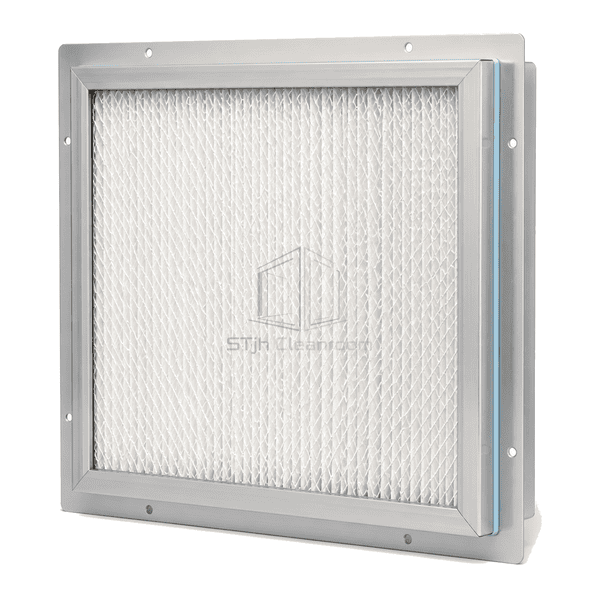
A cleanroom ceiling ULPA panel configured for direct final-air delivery from terminal housings or fan filter units into ultra-clean production zones.
- Ceiling-Terminal Format
- Uniform Downstream Face
- Shallow Mini-Pleat Pack
- Gasket or Gel Interface
Introduction de produit
The terminal ULPA filter forms the final filtration surface between a ceiling housing or fan filter unit and the cleanroom. Ultra-fine mini-pleat media is bonded into a shallow anodized-aluminium frame with a clean downstream protective grid. The frame can include a flat gasket land, a gel trough or an integral knife edge to match the terminal module. A smooth discharge face and balanced pack geometry help distribute low-turbulence air across process zones, work benches and mini-environments without adding a separate downstream duct section.
Key Features
A clean downstream grid protects the pleats and presents a uniform visible ceiling surface.
Balanced mini-pleat geometry supports even face velocity across the occupied terminal area.
Gasket, gel and knife-edge frame profiles match common ceiling housings and fan filter units.
Préoccupations du client produit
The last filtration stage must integrate cleanly with the ceiling, seal around the full perimeter and deliver uniform air directly into the controlled zone.
A remotely installed final filter allows duct leakage downstream of the filtration stage.Terminal mounting places the ULPA pack at the cleanroom boundary and shortens the clean side of the air path.
Uneven filter-face velocity disturbs sensitive work directly below the ceiling.Balanced pleat distribution and an open downstream grid promote a more uniform discharge pattern.
The filter frame does not match the ceiling housing's sealing method.Dry-gasket, gel-trough and knife-edge profiles cover the principal terminal interface types.
Exposed pleats are damaged during ceiling cleaning.A flush cleanable faceguard separates the media from routine wipe-down contact.
Les applications typiques
Semi-conducteurs Cleanroom PlafondsFan filter unit arraysUltra-clean process benchesPharmaceutical critical zonesPrecision assembly mini-environments
Paramètres techniques
Representative construction ranges for ceiling-terminal ULPA panels are shown below.
| Matériaux de base | Ultra-fine glass-microfibre or ePTFE ULPA media with mini-pleat separators |
|---|---|
| Panneau épaisseur | 69–150 mm overall terminal-filter depth |
| Largeur effective | 305 - 610 mm Largeur nominale du visage |
| Longueur maximale | Jusqu'à 1220 mm de longueur nominale du visage |
| Acier face épaisseur | 0.4–0.6 mm powder-coated or stainless-steel downstream faceguard |
| Densité Core | Approximately 30–50 kg/m³ equivalent ULPA mini-pleat pack density |
| Conductivité thermique | Approximately 0.032–0.045 W/(m·K) for the dry ULPA media pack |
| surface finie | Natural anodized aluminium with a clean white or stainless downstream grid |
| Type joint | Flat EPDM gasket, polyurethane gel channel or integral knife-edge terminal connection |
| Customisation | Disponible en fonction de l'application prévue et de l'environnement d'exploitation. |
Options disponibles
U15 or U16 mediaGlass-microfibre or ePTFE packDry gasket, gel trough or knife-edge frameWhite powder-coated or stainless downstream grid
Planning a Terminal ULPA Filter specification?
Envoyez-nous vos dimensions, conditions d'installation, objectifs de performance et finition de surface requise.