
 영어
영어 독일어
독일어 아랍어
아랍어 프랑스어
프랑스어 인도네시아어
 일본어
일본어 한국어현재 Current
 말레이어
말레이어 포르투갈어
포르투갈어 러시아어
러시아어 스페인어
스페인어 태국어
태국어 터키어
터키어 베트남어
베트남어

클린룸 유틸리티 시스템
밸브 manifold 패널
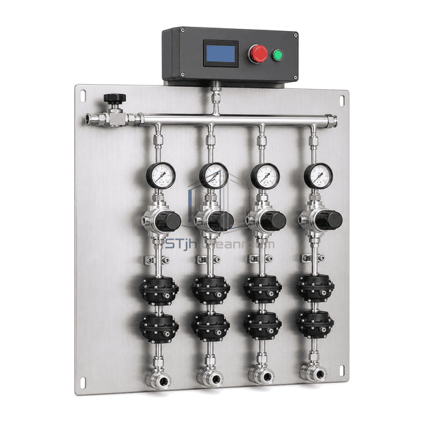
An open, wall-mounted four-stick UHP gas distribution panel that divides one compatible central supply into independently regulated and isolated process-tool branches without the footprint of an exhausted enclosure.
- Four modular pressure-controlled outlet sticks on one open backplate
- Independent branch isolation for service without a common shutdown
- Electropolished 316L flow path with selectable purge and control circuits
상품 소개
The Valve Manifold Panel is an exposed secondary distribution assembly for compatible inert or otherwise facility-approved high-purity gases. The selected catalogue configuration places one common inlet header and four parallel gas sticks on a rigid stainless mounting plate. Each stick has a compact pressure regulator, local pressure gauge, upstream and downstream diaphragm isolation valves, and one dedicated tool outlet. A compact controller above the backplate can supervise a normally closed common inlet valve and four branch shutdown signals. The open architecture gives technicians direct visual and service access where an exhausted containment box is not required by the gas hazard assessment. It has no cylinder, pigtail, cabinet or door and is distinct from a single-source pressure panel, an enclosed valve manifold box and a bare unregulated pipe manifold.
주요 기능
A dedicated regulator and gauge on each stick support different downstream delivery-pressure settings
Upstream and downstream diaphragm valves isolate one branch while the other qualified outlets remain available
Open component access shortens inspection, adjustment and planned replacement work in approved service areas
Electropolished 316L tubing and low-dead-volume diaphragm components help protect UHP gas cleanliness
A horizontal inlet header and aligned outlet interfaces simplify routing and permanent branch identification
Optional purge and evacuation circuits allow trapped branch volume to be displaced before maintenance
Modular stick spacing supports future branch population, component changes and gas-specific material selection
Optional common and stick-level normally closed valves provide defined automatic isolation points
The panel can be configured for manual, semi-automatic or monitored distribution without changing its open identity
고객 제품 관심사
An open valve manifold panel must match the gas hazard, preserve branch purity and make each pressure-control path serviceable without confusing shared and dedicated isolation boundaries.
One delivery-pressure setting cannot satisfy tools with different inlet limits or normal flow demandsSpecify a regulator range and local indicator for each stick, then commission every branch against its own downstream operating envelope.
Servicing a valve on one outlet can force an unnecessary shutdown of all connected equipmentPlace positive upstream and downstream isolation on every branch so the affected stick can be secured independently.
Residual gas and ambient moisture can enter the common header when a tool connection is openedUse a branch-specific compatible purge or evacuation path between the two isolation boundaries before disturbing the outlet joint.
An open panel may be selected for a gas that actually requires exhausted containmentLimit the VMP to gases and locations approved for open distribution; use an exhausted manifold box when the hazard review requires containment and airflow monitoring.
Mixed stick layouts make valve sequence, flow direction and outlet ownership difficult to verifyUse uniform component order, consistent flow arrows, permanent port tags and repeatable spacing across all four sticks.
A facility alarm may close the source but leave uncertain trapped volumes across individual branchesCoordinate the normally closed common inlet and selected stick shutdown valves with pressure feedback and a documented purge state for each outlet.
일반적인 응용 프로그램
Inert UHP gas distribution to multiple semiconductor process toolsNitrogen, argon and helium branch delivery in electronics clean manufacturingResearch-fab and university laboratory gas distribution with separately adjustable outletsLED, photovoltaic and compound-semiconductor process-tool hook-up systemsBiotechnology and pharmaceutical utility branches using compatible high-purity gasesAdvanced-material pilot lines where compact open service access is permitted
기술 매개변수
The catalogue basis follows the Stainless Design Concepts FlexGas four-stick VMP class: an open modular UHP panel approximately 470 mm wide, 533 mm high without the controller and 686 mm high with the selected control module. The wetted path uses electropolished 316L stainless tubing, diaphragm valves, regulators and service fittings, with one common inlet and four separately controlled outlets. Panel depth is configuration-dependent and a representative published envelope is approximately 222 mm. Gas compatibility, pressure range, flow, valve actuation, purge or evacuation method, filtration, instrumentation and automatic shutdown logic are selected for the actual service.
| 핵심 재료 | Open stainless mounting backplate with electropolished AISI 316L stainless tubing, regulators, diaphragm valves and fittings in the wetted flow path |
|---|---|
| 패널 두께 | 3.0 mm nominal rigid stainless mounting-panel thickness for the selected four-stick layout |
| 유효 폭 | 470 mm representative external panel width for the selected compact four-stick configuration |
| 최대 길이 | 686 mm representative overall panel height with the selected upper control module |
| 강철 면면 두께 | 3.0 mm nominal exposed brushed-stainless front mounting face thickness |
| 코어 밀도 | Approximately 8000 kg/m³ representative density for AISI 316L stainless flow-path components |
| 열전도도 (Thermal Conductivity) | Approximately 15 W/(m·K) near 20°C for representative AISI 316L wetted components |
| 표면 마무리 | Brushed natural-silver mounting plate with electropolished UHP wetted surfaces, typically 10 µin Ra (approximately 0.25 µm Ra) where specified |
| 접합 유형 | Orbital-welded 1/4 in. or 3/8 in. UHP tubing with metal face-seal service joints, one common inlet and four dedicated branch outlets |
| 사용자 정의 | 의도된 응용 프로그램 및 운영 환경에 따라 사용할 수 있습니다. |
사용 가능한 옵션
Four-stick or eight-stick open-panel arrangementsManual, semi-automatic or monitored branch operationStick-specific regulator ranges, gauges, pressure switches or transducersPurge-only, evacuation-only or combined purge-and-evacuation circuitsNormally closed common-inlet and individual-stick pneumatic valvesInlet filtration, point-of-use filtration or gas-specific purificationExcess-flow switches and branch shutdown inputsCompact touchscreen controller with dry contacts or selected facility communicationsGas-specific seals, alloys, high-flow components and face-seal connection sizes
Planning a Valve Manifold Panel specification?
치수, 설치 조건, 성능 목표 및 필요한 표면 마감을 보내십시오.